
- Main Features[edit]
- Types of PD Flowmeters[edit]
- Reciprocating Piston Meters [ edit ]
- Oval-gear Meters [ edit ]
- Nutating-disk Meters [ edit ]
- Rotary-vane Meters [ edit ]
- Helix Meters [ edit ]
- Sources[edit]
- General Components and Operation
- Benefits and Concerns
- Common Applications
- Professional Calibration Services
- Understand that All Flow Meters Require Regular Calibration
- Begin with Traceable Standards
- Understand Your Standard
- The Need for a Steady State
- Simultaneous Testing
- Calibrate Under Standard Operating Conditions
- Importance of Proper Calibration for Product Sales
- Poor Calibration and Safety
- PRINCIPLES OF OPERATION
- POSITIVE DISPLACEMENT FLOW METER CATALOG SHEET
- SPECIFICATIONS
- APPLICATIONS
- CONSTRUCTION
- Are DP Meters Accurate?
- Related Stories
- Reliability
- Low Maintenance
- Benefits Summary
- Limitations and Considerations
- Linear and Special Meters
- Performance
- Measurement of liquid fuel, oil, and combustion air consumption
- Positive-displacement flowmeters
- Instrumentation and control
- Positive-displacement Meters
- Measurement of Flow
- Rotary Piston
- General Instruments
- 4.3.2.3 Oval Gear Meter
- Natural Gas Measurement
- 16.3.1 Quantity Meters
- Process Control Systems
- VI.E Flow Measurements
- Measurement of fluid flow
- Turbine type flow meters
- Cup anemometer
- IMPLICATIONS OF OIL-REFRIGERANT INTERACTIONS FOR HEAT PUMP PERFORMANCE
- EXPERIMENTAL ARRANGEMENT
- Flow Measurement
- 16.3.3 Positive Displacement Flowmeters
Main Features[edit]
- Positive displacement type flowmeters usually offer high accuracy i.e. about ±0.1% of actual flow rate sometimes. Metering accuracy of the unit gets better with the increase in the process fluid viscosity.
- PD meters also provide excellent repeatability which can be as high as 0.05% of reading.
- PD meters can work without using a power supply. Moreover, they do not necessitate straight upstream and downstream pipe runs to install them.
- PD meters exist in size upto 12 in.
- Their turndown ratio can be as high as 100:1.
- Since PD meters have very small clearances between their precision-machined parts, rapid wear influences their accuracy. Therefore, these types of meters are normally not suggested for measurement of slurries or abrasive fluids.
- Positive displacement flowmeters are commonly employed as household water meters.
- Accuracy of positive displacement flowmeters depends upon the reliability of the capillary seal used to separate the passing liquid into discrete parcels. For getting the required accuracy and making sure that a PD meter works appropriately, a filtration system is needed. This filter system should be capable enough to remove large size particles as well as gas bubbles from the liquid flow.
- Positive displacement flowmeters works on a very simple operating principle. Positive displacement flowmeters consist of precision-fitted rotors for measurement of process fluid flow. Fixed volumes of liquid are moved between the rotors. The rotation of these rotors is directly proportional to the volume of the liquid being moved on.
- A central electronic pulse transmitter is included in a typical PD meter design which counts the number of rotations of the rotor. This counted number is then used to calculate liquid volume and flow rate.
- Rotor of a positive displacement type flowmeter can be constructed in numerous ways.
- Positive displacement flowmeters can be employed for nearly all nonabrasive fluids like heating oils, lubrication oils, polymer additives, animal and vegetable fat, printing ink, freon, etc..
Types of PD Flowmeters[edit]
PD flowmeters are mainly named after the inbuilt mechanical device in the meter unit. Various types of positive displacement flowmeters are available for industrial use. All these types are based on the common operating principle. Besides, they all are volumetric flow measuring devices. Major types of positive displacement flowmeters are mentioned below:
Reciprocating Piston Meters[edit]
These are also known as oscillating piston flowmeters. These are one of the oldest positive displacement type flowmeter designs. These types of meters are mainly of single or multiple-piston types. Other types available are double acting pistons and rotary pistons. Selection of a particular type of piston meter depends on the range of flow rates necessary for an application. Although piston meters are smaller in size and considered apt for handling only low flows of viscous liquids, yet they are proficient enough to deal with an extensive range of liquids. Major application areas of a reciprocating piston meter include viscous fluid services like oil metering on engine test stands, specifically where turndown ratio is not considered much crucial. Also these meters can be employed on residential water service where they tend to pass partial quantities of dirt and fine sand along with water.
Oval-gear Meters[edit]
These types of meters consist of two rotating, oval-shaped gears constructed with synchronized, close fitting teeth. In an oval gear meter, the rotation of gear shafts causes a fixed amount of liquid to pass through the meter. By monitoring the number of shaft rotations, one can calculate liquid flow rate. These types of meters prove to be very accurate when slippage between the housing and the gears is set very small. Turndown ratio of an oval gear meter gets influenced by the lubricating properties of the process fluid.
Nutating-disk Meters[edit]
These are the widely used positive displacement type flowmeters. They consist of a moveable disk which is positioned on a concentric sphere situated inside a spherical side-walled unit. Universally, they are employed as residential water meters. They exist in various sizes and capacities and can be constructed from a wide range of materials. Their typical size range varies from 5/8-in to 2-in sizes. They are ideal for pressure ranges around 150-psig with an upper limit of 300 psig.
Rotary-vane Meters[edit]
These types of meters do exist in different designs. However, they all work on the same operating principle. These meters basically include uniformly divided rotating impellers with two or more compartments inside the chamber. The number of rotations of the impeller are counted and recorded in volumetric units. These types of meters are frequently employed in the petroleum industry. Based upon the construction material, maximum pressure and maximum temperature limits of rotary vane meters are 350°F and 1,000 psig respectively. Their Viscosity limit ranges between 1 and 25,000 centipoise.ئشایه
Helix Meters[edit]
Sources[edit]
Omega.tech
Omega.literature
Engineeringtoolbox
efunda

Positive displacement flow meters are mechanical instruments that measure the volumetric flow rate of a fluid. The main advantage of these types of flow meters is their ability to handle high viscous and corrosive fluid, and they typically do not require filtration prior to processing. Here is a guide to positive displacement flow meters which includes an overview of the basic design, operation and benefits of this type of mechanical flow meter.
General Components and Operation
Though the details of each design vary, positive displacement flow meters all contain these major components:
- Inlet and outlet ports
- Measuring chamber
- One or more rotors
Fluid enters the measuring chamber through the inlet port and imparts energy on the rotor. The rotation of the rotor corresponds to the volume of fluid entering the chamber, and a signal is collected by the connected flow meter transmitter. The fluid then exits the chamber through the outlet port.
Two gears are commonly used as rotors for this type of flow meter. The gears can be aligned vertically or horizontally, and they can either be circular or oval shaped. In either case, the purpose of having two gears is to create a seal within the measuring chamber so that all fluid is measured before passing through. Other positive displacement flow meter designs may utilize two helical or screw-shaped gears, while some use one or more pistons or diaphragms to physically push fluid through the chamber.
Benefits and Concerns
Positive displacement flow meters are known for their accuracy, mainly due to the tight seal created within the mixing chamber. They can also measure a wide range of flow capacities and fluid characteristics. Gear meters perform well in lower flow applications, but can handle higher rates with accuracy. They also respond quickly to changes in flow conditions, so the time it takes to collect and transmit real-time data is relatively short.
The simplicity of the design makes these flow meters relatively low maintenance and easy to disassemble and reassemble. Disassembly typically only requires disconnecting electrical wiring, removing a few screws, lifting off the cover, removing an O-ring and unscrewing the rotors. Bearings may also be installed on the rotor shaft to support the load.
Since positive displacement flow meters contain mechanical components, the parts are susceptible to wear and damage over time and require replacement. Bearings typically do not require relubrication, or they are lubricated by the fluid being pumped. Gears and bearings may need to be replaced eventually depending on the solids content and type of solids present in the fluid.
Though the flow meters can be used for a variety of fluids, if large particles are present in the fluid, they should be filtered upstream to protect the mechanical components from damage. Also, for systems where cavitation is an issue or where air pockets are common within pumped fluid, air eliminators should be installed upstream of the flow meters to prevent damage and provide more accurate volumetric readings.
Pressure drops do occur across positive displacement flow meters, which must be accounted for in system calculations. Such pressure drops are usually minimal and therefore relatively insignificant. However, larger pressure drops can damage internal bearings and seals. Manufacturers typically define a maximum operating pressure value to prevent premature wear and potential flow meter failure. If the viscosity of the pumped fluid changes, check the pressure drop to ensure it still falls within the acceptable range.
Common Applications
Positive displacement flow meters can be used in a variety of industries. Some common applications include:
- Oil and gas
- Chemical and petrochemical transport
- Pharmaceutical
- Water and wastewater treatment and infrastructure
- Food and beverage manufacturing
- Aerospace
- Automotive
Such types of mechanical flow meters are also useful for batching, lubrication oil blending and hydraulic test stands.
Calibration is an important component of flow meter maintenance. A well-calibrated flow meter provides accurate readings and helps operators keep the system running efficiently. Though calibration procedures for gas and liquid flows follow the same underlying principles, the methods for calibration are different. For liquid applications, there are various ways to calibrate a positive displacement flow meter such as:
- Standing start and stop method, also known as the bucket and stopwatch method
- Flying start and stop method
- Dynamic methods that calibrate during continuous flow conditions
To calculate the volume and mass of collected liquid during the calibration procedure, either gravimetric calibrators or volumetric calibrators are used.
Other types of calibration devices can be installed along the pipeline to measure the flow meter performance in-situ. For example, pipe provers can be installed in sealed pipelines to measure the accuracy of the flow meter without interrupting the process. This is a dynamic calibration that continuously compares the flow meter measurement to a standard.
Gas applications require different calibration methods due to the compressibility of the fluid. Examples of gas calibration methods include:
- Prover methods, which work like pipe provers for liquid applications
- Gas displacement methods
- Sonic nozzle methods, which use a Venturi-style nozzle to determine flow accuracy
Professional Calibration Services
Though calibration should be incorporated as part of regularly scheduled instrumentation maintenance, it is difficult to determine the best frequency of calibration. Therefore, it is helpful to hire a third-party who specializes in flow meters and flow meter calibrations to determine a schedule that it appropriate for each system.
Professional flow meter calibration services use advanced methods to more accurately determine the performance of flow meters. Such professionals are knowledgeable about the tolerance levels for each type of flow meter and can identify and interpret errors in the calibration procedure. They can also help identify system issues from the calibration results. For example, calibration data may indicate leaks or damaged internal components that need to be replaced. Professional services can also look at the history of calibration to identify significant system changes or make recommendations based on changes to the characteristics of the flow.
Overall, positive displacement flow meters last for many years when the right flow meter is chosen for the application, proper flow conditions are maintained and the flow meter is calibrated at regular intervals.

A flow meter is a device designed to measure the rate of flow of a fluid through a space within a larger system. In fact, the use of flow meters is incredibly common amongst businesses and other organizations including:
- Agriculture
- Aerospace
- Chemical
- Petrochemical
- Water Utilities
However, a flow meter must be calibrated properly to ensure the readings are accurate. Often, this requires referencing specific calculations and measurement standards that are set by the industry, in which the company is doing business. Regular calibration ensures that each meter is providing reliable outputs. Typically, calibrating involves making a series of small adjustments based on comparing the readings of the flow meter being calibrated and the flowrate measured by a meter that is known to be accurate.
To support proper calibration of a positive displacement flow meter, it is best to follow a series of best practices associated with performing the actions needed.
Understand that All Flow Meters Require Regular Calibration
It is important to first understand that all flow meters require calibration on a regular schedule, as well as when outputs seem inaccurate. Even the most well-made and sophisticated flow meters degrade over time, resulting in lower accuracy.
For example, corrosion or debris buildup can dramatically impact outputs, and a positive displacement flow meter can be subject to either depending on the fluid being measured and the surrounding operating conditions. With that in mind, the only way to ensure accuracy over the long term is to perform maintenance as required.
Begin with Traceable Standards
Often, it is best to use a traceable standard when calibrating equipment. This means using measurements associated with known national standards. By adhering to the standards set forth by an industry organization, each business knows they are operating within the same level of accuracy and, when applicable, providing similar outputs to customers.
Understand Your Standard
Before calibrating a positive displacement flow meter, it is best to aim for an end result that is at a higher standard than you actually need to achieve. By looking to reach an accuracy of approximately four times the level required based on the unit under test, you can lower the frequency at which calibration needs to be repeated. It also confirms your output is safely within an acceptable range which is critical when dispensing products for customers.
The Need for a Steady State
Calibrating the rate of flow of a fluid through a flow meter requires the materials to pass through at a steady rate. Since calibration is completed in real-time based on the experience rate of output being compared to a known standard, fluctuations in the flow rate will make the task more challenging. By selecting a specific flow rate, the process is simplified as it removes an inconsistency from the equation.
Additionally, using a varying rate of flow may lead to an incorrect calibration. This means that, even when the steps are complete, the associated operations may not be meeting the required standards.
Simultaneous Testing
When measuring the flow rate for the purpose of calibrating a positive displacement flow meter, it is important to use the known standard device simultaneously with the one being calibrated. This method reduces the impact of certain variables that may shift over time. For example, the temperature of a fluid can affect its viscosity. This changes the rate at which the fluid will flow through the positive displacement flow meter and can affect the accuracy of the results.
Calibrate Under Standard Operating Conditions
Another component of the calibration process that can increase the accuracy of the end result involves performing the actions in circumstances that mimic standard operating conditions. Flow meters will experience the vast majority of their use during situations that are present during daily operations. By copying the environmental conditions present during those times, you can measure accuracy during the calibration process based on business norms.
Certain factors can have a major impact on flow rates of liquids, such as relative humidity and ambient temperature, so calibrating conditions should mirror those typically present. Additionally, if other mechanical operations or measuring equipment are normally in use in the area, these should be operating during positive displacement flow meter calibrations as well.
Importance of Proper Calibration for Product Sales
A common use of a flow meter is to ensure the proper amount of product is dispensed to customers. Improperly calibrating the positive displacement flow meters involved in these situations means the output does not match what has been purchased. Inaccurate high readings mean the amount of fluid provided during a sale may actually be less than what was purchased, resulting in customers being shortchanged during the transaction. Over time, this can lead to a poor business reputation.
If overly low readings occur, the output will exceed the amount purchased. This means the business is losing profit since the product is being sent out the door even though it wasn’t purchased.
Poor Calibration and Safety
Since flow meters are used in certain mechanical processes, such as in combustion engines, failing to properly monitor the rate of flow can actually present a danger. Following the engine example, inaccurate readings regarding fuel output can result in engine failure or damage. And, should an engine fail while it is in operation, any person in the vicinity may be harmed.
Even in cases where damage to the side is the only byproduct, it could increase the frequency at which maintenance must be performed as well as how quickly the equipment must be replaced. Overall, this leads to increased expenses and decreased efficiency.
Most positive displacement flow meters are designed to be calibrated on a specific schedule. Generally, this information is provided by the manufacturer to ensure the accuracy of their products. However, in cases where it is obvious the readings are no longer accurate, calibration should be completed at that time instead of waiting for the next scheduled maintenance point. That way, your equipment, and your business can operate at peak efficiency at all times.

PRINCIPLES OF OPERATION
The force of the liquid moving through the flow meter drives the measuring gears. The liquid stream is divided into the fixed volume cavities between the gear teeth and metering body.
The movement of gear is measured by means of a pick-up sensor located in the cover. When the measuring gears rotate by one tooth pitch, the sensor emits a signal/frequency, which corresponds to the geometrical tooth volume. The signal is converted into a square wave pulse by the pre-amplifier.
The pulse or frequency output are processed by secondary instruments ranging from a basic signal conditioner, indicator/totalizer to more complex flow computers, which compensate temperature, pressure, density, viscosity and provide accurate volumetric or mass flow measurement.
POSITIVE DISPLACEMENT FLOW METER CATALOG SHEET

SPECIFICATIONS
- Maximum operating pressure: 6000 psi
- Available sizes from 1/4″ to 1-1/2″
- Temperature Limits: -40°F to 400°F (-40°C to 204°C)
- Flow Range: .01 -110 GPM
- Accuracy: +/- .05% of Reading

APPLICATIONS
- Hydraulic Test Stands (Low Viscosity)
- Aerospace and Automotive (Low to Medium Viscosity)
- Batching and Mixing (Medium Viscosity)
- Petrochemical (Medium to High Viscosity)
- Lubrication Oil Blending (High Viscosity)

CONSTRUCTION
- HOUSING: 304 Stainless Steel
- COVER: 304 Stainless Steel
- GEAR: 416 Stainless Steel
- PICKUP SENSOR: 303 Stainless Steel Housing with Solid Epoxy Encapsulation
- MATING CONNECTOR: MS 3102A-10SL
- BEARING: 440C Stainless Steel
Are DP Meters Accurate?
One of the key benefits of using a PD flow meter is the level of accuracy that can be obtained, and the high precision from the internal components means that clearances between sealing faces is minimal. How small these clearances are, is relative to how high the accuracy will be. Only the fluid that can bypass this seal is not counted, this is known as ‘by-pass’ or ‘slippage’.
.jpg)
Related Stories
Rotating Positive Displacement flow Meters
Reliability
If the right flowmeter has been chosen for a given application, it is expected to perform without error for many years. PD flow meters are often sent for servicing and recalibration, with many instruments having been in the field for 10, and in a lot of cases, 20 years continuous use. This reliability is largely due to this proven technology being in use for over 60 years and has allowed for the significant advances to be concentrated within the fields of tribology, as well as achieving the required precision at an affordable cost.
Low Maintenance
The required amount of maintenance is heavily reliant on the application. For example, if a flow meter processes a fluid that displays lubrication properties, i.e. oil, then the requirement for maintenance is virtually non-existent. However, if the fluid has poor lubricating properties, then the maintenance requirements will need to be discussed with your distributor and/or expert. It is not common that maintenance to a positive displacement flow meter would be more frequent than other instruments within the same system. Any such maintenance can be scheduled to be carried out at the same time as the other components, thus reducing the downtime.
.jpg)
Positive Displacement Flow Meter for Industrial Processes
.jpg)
Positive Displacement Flow Meter for Fuels and Oils
Benefits Summary
- High level of accuracy (0.5% as standard) higher level of accuracy available upon request
- Ability to process a large range of fluid viscosities <1 cP – >500000 cP
- Low maintenance
- High pressure capabilities
- Electronic and mechanical versions available
- Spare parts availability
Limitations and Considerations
Although positive displacement flow sensors are very robust, they do possess some downsides. Firstly, they should not be used for fluids containing large particles, unless they undergo a pre-filtering process before entering the measurement chamber. They are also unsuitable for applications where large amounts air are present within the fluid; however, air eliminators are available for such applications. One factor that requires serious consideration, is the pressure drop caused by the PD meter; even though it is minimal, they should be factored in for system calculations. As mentioned above, when using processing fluids with poor lubricating properties, it is recommended that advice is first sought from your distributor; various options are available for these applications.

This information has been sourced, reviewed and adapted from materials provided by OMEGA Engineering Ltd.
For more information on this source, please visit OMEGA Engineering Ltd.
Linear and Special Meters
Paul J. LaNasa, E. Loy Upp, in Fluid Flow Measurement (Third Edition), 2014
Performance
PD meters perform well for long periods of time provided the fluids are clean, non-erosive, non-corrosive, non-depositing, and proper maintenance is routinely performed. Most major manufacturers also offer special designs for “hostile” fluids. In less critical measuring systems, such as domestic water and gas, meters are run for many years with testing only on the basis of statistical failure-rate study or upon customer complaint.
On the other hand, large liquid PD meters used in the petroleum industry may be tested on a weekly basis with a prover system permanently installed as part of the metering station.
There should be no overranging; if necessary, a protective flow-limiting device (with automatic bypass valve) should be installed to prevent the overranges, which mechanically damage the meter.
Read full chapter
URL:
Measurement of liquid fuel, oil, and combustion air consumption
Anthony J. Martyr, David R. Rogers, in Engine Testing (Fifth Edition), 2021
Positive-displacement flowmeters
Positive-displacement meters provide high accuracy, ±0.1% of actual flow rate is claimed, and good repeatability. Their accuracy is not affected by pulsating flow and many designs do not require a power supply nor lengths of straight pipe upstream and downstream in their installation. Their main disadvantage is the appreciable pressure drop required to drive the metering unit, which may approach 1 bar. The process fluid must be clean because they operate with small clearances; particles greater than 100 µm must be filtered out upstream of the unit.
Several designs of positive-displacement (volumetric) fuel gauges make use of a four-piston metering unit with the cylinders arranged radially around a single-throw crankshaft. Crankshaft rotation is transmitted magnetically to a pulse output flow transmitter. Cumulative flow quantity and instantaneous flow rate are indicated, and these meters are suitable for in-vehicle use. A turndown ratio as high as 100:1 is claimed in some designs.
Read full chapter
URL:
Instrumentation and control
In The Efficient Use of Energy (Second Edition), 1982
Positive-displacement Meters
Positive-displacement meters, as their name implies, respond directly to movement of liquid and are capable of measuring flow rate to an accuracy better than ±0.1% and repeatability ±0.01%. They are commercially referred to as bulkmeters and are particularly suited to applications such as aviation refuelling, ship bunkering, tank calibration, engine test rigs, proving other forms of metering, and blending processes. Typical examples of meters for such applications are manufactured by Wayne Tank and Pump Co., and Avery Hardoll on whose basic range these notes have been compiled. A typical positive-displacement meter is shown sectioned in Figure 51.

Figure 51. Positive displacement meter. Principle of operation
It comprises a casing containing a rotor assembly fitted with four blades in opposing pairs, each pair being mounted on rigid tubular rods. Above the rotor casing is bolted an inlet and outlet manifold whilst a calibrating mechanism and direct-reading mechanical counter are bolted on the front cover. The only moving parts within the fluid being metered are the rotor and rotor blades, which are constantly immersed.

Figure 52. Typical accuracy curves for bulkmeters
Reference has been made to a calibrating mechanism interposed between the rotor shaft and readout counter. The unit comprises a stepless friction wheel and disc, the ratio being adjusted by means of a calibration screw. On BM series meters one complete turn of the screw alters the calibration by approximately 0.1% while similar rotation on LBM meters alters the calibration by 0.23%. Thus, calibration adjustment can be effected at any chosen flow rate and this feature, coupled with an inherent repeatability of ±0.01%, enables very accurate readings to be taken.
For temperature compensation, a compensator can be supplied which automatically adjusts the indicated volume on the counter to an equivalent volume at the recognized standard temperature (60°F or 15°C). If another ‘standard’ temperature is required in special circumstances, the temperature compensator can be calibrated accordingly. The unit is not affected by ambient temperature and the response time is some 15 s depending on fuel characteristics. This development enables the range of bulkmeters to be used for applications such as the loading of heated oils.
The unit is shown schematically in Figure 53, and basically consists of a temperature-sensitive fluid reservoir tube which is connected to a bellows compartment, the assembly being immersed in the liquid being metered. Any temperature variation from standard is immediately sensed by the reservoir tube which is transformed by the bellows into linear movements. This movement, through levers, adjusts the existing bulkmeter calibrating mechanism by repositioning a friction wheel on a disc. Because the temperature-sensitive components are fully immersed in the liquid being metered, they are not affected by atmospheric temperature. As the cubical expansion coefficient differs from liquid to liquid, a dial and knob are fitted to the front cover of the unit for adjustment as necessary. The dial is graduated in coefficients of expansion and a pointer on the dial is set to the appropriate position by the knob. Rotating the knob also adjusts a variable fulcrum lever so that the friction-wheel movement is in proportion to the coefficient of expansion of the liquid concerned for a given temperature rise. The knob is normally locked in position and can be sealed by Customs authorities.

Figure 53. Diagrammatic arrangement of temperature compensating unit
In addition to local direct reading of volume, fully flameproof transmitters are available for remote digital read-out of volume or rate of flow, and remote analogue read-out of rate of flow. These transmitters enable positive displacement meters of the type described to be incorporated as the primary sensing elements in a variety of system applications, e.g. preset systems, servo blending systems, railcar loading and road-tanker loading.
Alternative forms of transmitters available are described in the following paragraphs.
Read full chapter
URL:
Measurement of Flow
G. Fowles, W.H. Boyes, in Instrumentation Reference Book (Fourth Edition), 2010
Rotary Piston
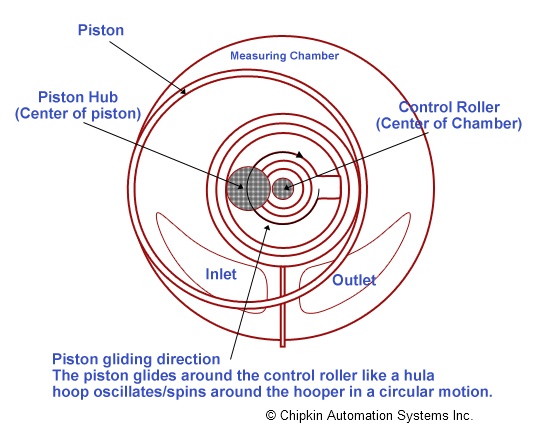
The rotary-piston flowmeter is most common in the water industry, where it is used for metering domestic supplies. It consists of a cylindrical working chamber that houses a hollow cylindrical piston of equal length. The central hub of the piston is guided in a circular motion by two short inner cylinders. The piston and cylinder are alternately filled and emptied by the fluid passing through the meter. A slot in the sidewall of the piston is removed so that a partition extending inward from the bore of the working chamber can be inserted. This has the effect of restricting the movement of the piston to a sliding motion along the partition. The rotary movement of the piston is transmitted via a permanent-magnet coupling from the drive shaft to a mechanical register or electronic readout device. The basic design and principle of operation of this meter is shown diagrammatically in Figure 6.16.

FIGURE 6.16. Rotary-piston positive displacement meter. Courtesy of ABB Instrument Group. 1. Lid. 2. Hinge pin. 3. Counter housing complete with lid and hinge pin. 4. Counter with worm reduction gear and washer. 5. Counter washer. 6. Ramp assembly. 7. Top plate assembly comprising top plate only; driving spindle; driving dog; dog retaining clip. 8. Piston. 9. Shutter. 10. Working chamber only. 11. Locating pin. 12. Strainer-plastic. Strainer-copper. 13. Strainer cap. 14. Circlip. 15. Nonreturn valve. 16. O ring. 17. Chamber housing. 18. Protective caps for end threads.
Read full chapter
URL:
General Instruments
Swapan Basu, Ajay Kumar Debnath, in Power Plant Instrumentation and Control Handbook (Second Edition), 2019
4.3.2.3 Oval Gear Meter
The oval gear meter is a also a type of positive displacement meter. The operating principle of the oval gear meter is based on two or more oval-shaped gears configured to rotate always at right angles to one another. It has two sides connected to the inlet and outlet ports. The teeth of the two gears always mesh, so fluid is not allowed to pass through the center of the meter. At one position of the inlet side gear, the teeth of the gear shut the fluid flow inlet because the elongated gear is protruding into the measurement chamber. At that time, at the outlet side of the meter, a cavity is formed that holds a fixed amount of fluid in the measurement chamber.
Read full chapter
URL:
Natural Gas Measurement
Saeid Mokhatab, … John Y. Mak, in Handbook of Natural Gas Transmission and Processing (Fourth Edition), 2019
16.3.1 Quantity Meters
Quantity meters are also classified as positive displacement. Some of the more common positive displacement meters are as follows: reciprocating piston, rotating piston, nutating disk, sliding and rotating vanes, gear and lobed impeller, and the meter most commonly used to sell small quantities of gas at relatively low flow rates, the bellows meter (Daniel Measurement and Control Inc, 2017).
In the reciprocating or rotating piston meter as shown in Fig. 16.1 the fluid enters through an inlet port. The port leads to a precisely measured gap created by a piston in a round chamber. As the piston oscillates around the chamber by mechanical or magnetic means, each stroke displaces an exact volume of fluid.

Figure 16.1. Reciprocating piston meter.
Source: Omega Engineering.
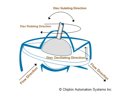
A nutating disc flow meter as shown in Fig. 16.2 has a round disc mounted on a spindle in a cylindrical chamber. The disk is oscillated around the axis of the cylinder by the fluid flow, and each rotation represents a finite amount of fluid transferred. By tracking the movements of the spindle, the flow meter determines the number of times the chamber traps and empties fluid. This information is used to determine flow rate.

Figure 16.2. Nutating disc flow meter.
Source: Protorit.
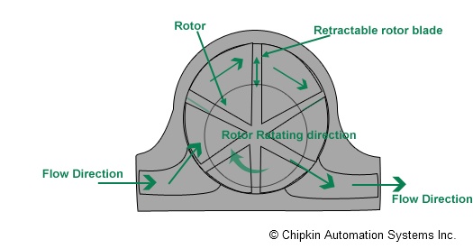
A rotary or sliding vane meter as shown in Fig. 16.3 contains a circular rotor mounted inside a round compartment that holds a number of sliding vanes. The vanes isolate fixed volumes of fluid between the rotor and the wall of the compartment. The center of the rotor is offset from that of the compartment to keep the rotor in constant contact with the wall of the compartment opposite to that of the pockets to prevent backwashing.

Figure 16.3. Rotary vane meter.
Source: Chipkin Automation Systems.
Lobed or gear impeller flow meters, as shown in Fig. 16.4, consist of two impellers rotating in opposite directions due to the forces exerted by the measured gas flow. The placement of the impellers prevents contact while the gap between them remains the same. A gear drive synchronizes the impellers. The number of rotations is proportional to the flow.

Figure 16.4. Oval gear meter.
Source: Badger Meter, Inc.
Bellows are the most common type of gas meters, seen in almost all residential and small commercial installations (Fig. 16.5). Within the meter, there are two or more chambers formed by movable diaphragms (refer to Fig. 16.6). The gas flow is directed by internal valves to alternately fill the chambers and expel gas producing a near continuous flow through the meter. As the diaphragms expand and contract, levers connected to cranks convert the linear motion of the diaphragms into rotary motion of a crank shaft that serves as the primary flow element. This shaft can drive an odometer-like counter mechanism, or it can produce electrical pulses for a flow computer.

Figure 16.5. Residential gas meter.
Source: American Meter Company.

Figure 16.6. Bellows meter operations.
Source: American Meter Company.
Read full chapter
URL:
Process Control Systems
Juergen Hahn, Thomas F. Edgar, in Encyclopedia of Physical Science and Technology (Third Edition), 2003
VI.E Flow Measurements
Flow is defined as the volume per unit of time passing through a given cross-sectional area at a specified temperature and pressure. Flow is generally measured by either positive displacement or rate meters. The term positive displacement refers to a device in which the flow is divided into isolated measured volumes and the number of fillings of these volumes is counted in some manner. The term rate meter applies to all types of flowmeters through which the material passes without being divided into isolated quantities. The movement of the material is usually measured by a primary measurement element that activates a secondary device. The flow rate is then inferred from the output of the secondary device. Flow measurement devices include orifice meters, venturi meters, rotameters, turbine meters, vortex-shedding flowmeters, ultrasonic flowmeters, magnetic flowmeters and coriolis flowmeters. In each case the nature of the flowing material, the cost of the instrument, and necessary accuracy determine the choice of the flow measuring device.
Read full chapter
URL:
Measurement of fluid flow
J O Bird BSc, CEng, MIEE, CMath, FIMA, FCollP, MIEIE, P J Chivers BSc, PhD, in Newnes Engineering and Physical Science Pocket Book, 1993
Turbine type flow meters
- 11
Turbine type flow meters are those which use some form of multi-vane rotor and are driven by the fluid being investigated. Three such devices are the cup anemometer, the rotary vane positive displacement meter and the turbine flow meter.
Cup anemometer
- (a)
An anemometer is an instrument which measures the velocity of moving gases and is most often used for the measurement of wind speed. The cup anemometer has 3 or 4 cups of hemispherical shape mounted at the end of arms radiating horizontally from a fixed point. The cup system spins round the vertical axis with a speed approximately proportional to the velocity of the wind. With the aid of a mechanical and/or electrical counter the wind speed can be determined and the device is easily adapted for automatic recording.
- (b)
Rotary vane positive displacement meters measure the flow rate by indicating the quantity of liquid flowing through the meter in a given time. A typical device is shown in section in Figure 49.8 and consists of a cylindrical chamber into which is placed a rotor containing a number of vanes (six in this case). Liquid entering the chamber turns the rotor and a known amount of liquid is trapped and carried round to the outlet.

Figure 49.8.
If x is the volume displaced by one blade then for each revolution of the rotor in Figure 49.8, the total volume displaced is 6x. The rotor shaft may be coupled to a mechanical counter and electrical devices which may be calibrated to give flow volume. This type of meter in its various forms is widely used for the measurement of domestic and industrial water consumption, for the accurate measurement of petrol in petrol pumps and for the consumption and batch control measurements in the general process and food industries for measuring flows as varied as solvents, tar and mollases (i.e. thickish treacle).
- (c)
A turbine flow meter contains in its construction a rotor to which blades are attached which spin at a velocity proportional to the velocity of the fluid which flows through the meter. A typical section through such a meter is shown in Figure 49.9 The number of revolutions made by the turbine blades may be determined by a mechanical or electrical device enabling the flow rate or total flow to be determined.

Figure 49.9.
Read full chapter
URL:
IMPLICATIONS OF OIL-REFRIGERANT INTERACTIONS FOR HEAT PUMP PERFORMANCE
J.T. McMullan, in Energy Developments: New Forms, Renewables, Conservation, 1984
EXPERIMENTAL ARRANGEMENT
The fundamental objective of this project was to investigate the effects of varying the oil circulation in the evaporator and in the compressor of a heat pump system. The test rig therefore consists of a water-to-water heat pump which provides facilities for varying the oil concentrations as required. It also provides the essential facilities for recovering the oil and refrigerant from the liquid which has been removed from the heat pump. The design is an extension and development of a previous system which has been described elsewhere (3). The underlying scheme is a water-to-water heat pump, with an oil injection stage in the condenser liquid line, two liquid separation stages in the compressor suction and discharge lines, and two oil and refrigerant recovery systems. Figure 1 shows the layout of the system, though for simplicity, only the evaporator oil circuit is shown (the compressor oil circuit is virtually identical). The test rig is extensively instrumented and is microcomputer controlled to ensure the stability of the operating conditions. This of itself is not a trivial operation, as the system involves a number of dynamically interactive loops, which makes precision control of its behaviour difficult to achieve. Further complications arise when account is taken of the general requirement to make calorimetric measurements to acceptable accuracy (that is, to better than 5%), and of the particular need in this work to determine the fluid state points accurately, especially at the evaporator outlet. The result of this is that temperature and pressure measurements must be made with a precision which is not normally fully appreciated. Typically, temperature must be known to within 0.1 K and pressure to within 1.6 kPa.

Fig. 1. Schematic diagram of test rig showing evaporator oil circuit
The data acquisition system has two distinct functions to perform. The first is the routine logging and conditioning of the data signals from the rig. This involves the handling of a relatively large volume of data at time intervals which are normally between 1 and 30 minutes, but which may be as low as 10 seconds as this is the default scan time of the microcomputer data logging and control program.
The total data logging burden was:
- –
31 temperatures using single or multiple thermocouples
- –
3 differential temperatures using thermopiles
- –
7 pressures using strain gauge bridge pressure transducers
- –
14 fluid flows using axial turbine or positive displacement meters
- –
3 electrical power measurements using modified eddy current kWh meters.
This represents a total of 41 analogue and 17 digital signals, of which, depending on the operating mode, up to 10 (6 analogue, and 4 digital) are needed to perform the control function.
Since 58 analogue and digital signals have to be monitored regularly, and ideally simultaneously, it was decided to use a micro-processor based data acquisition and processing system. Commercially available systems were examined, but were found to have three major disadvantages – insufficient accuracy in most cases, inflexibility, and lack of a suitably comprehensive control function. Thus, the system shown in Figure 2 was developed in our own laboratory.

Fig. 2. Schematic diagram of control and data logger hardware
An Apple ][ microcomputer was used as the basis of this system, primarily because of its flexibility and the ease with which custom designed hardware can be interfaced with it. The data acquisition system is shown in Figure 3, where it can be seen that the organisation is different for the digital and analogue data channels.

Fig. 3. Signal conditioning and multiplexing system
Each digital data channel consists of a frequency counter which monitors the pulse rate from a sensor, and latches it after a suitable interval. During the computer read cycle the output latches are scanned sequentially. The time required to scan all of these 16 bit channels is less than 1 ms.
The analogue signals are more complicated because they involve A-to-D conversion, and so must be preconditioned to a voltage range which suits the A-D converter. The amplification requirements vary from channel to channel. A particular complicating factor arises with the thermocouples, where the required absolute accuracies are in microvolts. This implies the use of high gain, very low drift amplifiers. Experience has shown that using a dedicated high precision amplifier for each channel is not the best approach. No matter how well they are matched, no two amplifiers are identical. It is preferable to multiplex all sensors with similar requirements into a common amplifier. This has the secondary advantage that calibration signals can be included with the data set, and sampled at every scan, thus overcoming any remaining amplifier drift problems.
The analogue channels are therefore arranged in groups of 16, with one precision instrumentation amplifier per group. The signals are multiplexed into the amplifier by relays with gold-plated contacts, and the amplifiers themselves are multiplexed into a single 12-bit dual slope A-D converter which is read by the microcomputer. In principle, the multiplexer control bus gives access to 65536 separate channels, however, in the present installation, only 256 of these are used.
After analysing this data, the microcomputer generates signals to position the control valves on the test rig. These signals are transmitted via a multichannel D-A system which produces command signals for the valve motor controllers. In this way, the function of valve positioning is off-lined from the computer, thus saving valuable computation time. The control philosophy adopted is very simple. The control signal for each channel is determined from the appropriate error signals for that channel using a proportional term to allow for the current deviation of the controlled parameter from its set point, and an integral term to cancel the droop from the set value that always appears with proportional control systems. The differential control term is also calculated but has been found to be unnecessary. The control signals for the various channels are evaluated independently and there is assumed to be no interaction between channels. There is actually considerable interaction between the various channels (for example, the condensing and evaporating temperatures), however, the system functions well and provides adequate control for present purposes.
The coefficients in the control algorithms for each channel were determined from measurements of the appropriate critical proportional gain and the system time constant. This process was conducted for each channel independently and the resulting coefficients were modified as necessary to compensate for the interactions between the channels. This approach is far from ideal but leads to the desired result.
Up to eight parameters may be controlled, and currently the evaporator temperature and superheat, the condensing temperature, the evaporator oil injection rate are used. Other possibilities include the rate of oil injection to the compressor system, the degree of refrigerant liquid subcooling at the expansion valve inlet, the water flow rates to the heat exchangers, the temperature and flow rate of liquid refrigerant injected into the compressor, and so forth.
A useful feature of the system is that selection of a particular control scenario is achieved at run time merely by choosing the appropriate software. In practice, this means selecting a particular floppy disk.
The microcomputer software performs the following sequence:
- 1.
Test keyboard for operator intervention.
- 2.
Read the clock and delay until the next scan time (10 seconds).
- 3.
Read the data from all channels.
- 4.
Convert the raw binary data to the appropriate physical values, taking account of all current conversion and calibration factors.
- 5.
Calculate new values for the control signals and send them to the output D-A converter for transmission to the valve controllers.
- 6.
Display the currently selected set of parameters on the monitor screen. It is possible to select one of a number of different screen displays by pressing a key under 1. above.
- 7.
Store the processed data for subsequent time averaging. This is used to eliminate the effects of random fluctuations.
- 8.
At the required time, perform data averaging, store on diskette, transmit to the mainframe computer for analysis and archiving.
- 9.
Repeat this sequence.
It is worth noting that interfacing to a timeshared mainframe computer is not a trivial problem, and has entailed an extensive hardware and software development programme to ensure that it is accomplished reliably and efficiently. We have developed a special microprocessor based system (shown as Apple #2 in Figure 2) which gives extensive data buffering, and provides detailed on-line analysis and graphics capabilities. One result of this is that, typically within 20 seconds, data can be collected from the test rig, analysed using the power of the mainframe computer, saved to disk and displayed on VDU screen or printer in the laboratory.
Read full chapter
URL:
Flow Measurement
Alan S. Morris, Reza Langari, in Measurement and Instrumentation, 2012
16.3.3 Positive Displacement Flowmeters
Positive displacement flowmeters account for nearly 10% of the total number of flowmeters used in industry and are used in large numbers for metering domestic gas and water consumption. The least expensive instruments have a typical inaccuracy of about ± 2%, but the inaccuracy in more expensive ones can be as low as ± 0.5%. These higher quality instruments are used extensively within the oil industry, as such applications can justify the high cost of such instruments.
All positive displacement meters operate using mechanical divisions to displace discrete volumes of fluid successively. While this principle of operation is common, many different mechanical arrangements exist for putting the principle into practice. However, all versions of positive displacement meters are low friction, low maintenance, and long life devices, although they do impose a small permanent pressure loss on the flowing fluid. Low friction is especially important when measuring gas flows, and meters with special mechanical arrangements to satisfy this requirement have been developed.
The rotary piston meter is a common type of positive displacement meter used particularly for the measurement of domestic water supplies. It consists, as shown in Figure 16.8, of a slotted cylindrical piston moving inside a cylindrical working chamber that has an inlet port and an outlet port. The piston moves round the chamber such that its outer surface maintains contact with the inner surface of the chamber, and, as this happens, the piston slot slides up and down a fixed division plate in the chamber. At the start of each piston motion cycle, liquid is admitted to volume B from the inlet port. The fluid pressure causes the piston to start to rotate around the chamber, and, as this happens, liquid in volume C starts to flow out of the outlet port, and also liquid starts to flow from the inlet port into volume A. As the piston rotates further, volume B becomes shut off from the inlet port, while liquid continues to be admitted into A and pushed out of C. When the piston reaches the end point of its motion cycle, the outlet port is opened to volume B, and the liquid that has been transported round inside the piston is expelled. After this, the piston pivots about the contact point between the top of its slot and the division plate, and volume A effectively becomes volume C ready for the start of the next motion cycle. A peg on top of the piston causes a reciprocating motion of a lever attached to it. This is made to operate a counter, and the flow rate is therefore determined from the count in unit time multiplied by the quantity (fixed) of liquid transferred between inlet and outlet ports for each motion cycle.

Figure 16.8. Rotary piston form of positive displacement flowmeter.
The nutating disk meter is another form of positive displacement meter in which the active element is a disc inside a precision-machined chamber. Liquid flowing into the chamber causes the disc to nutate (wobble), and these nutations are translated into a rotary motion by a roller cam. Rotations are counted by a pulse transmitter that provides a measurement of the flow rate. This form of meter is noted for its ruggedness and long life. It has a typical measurement accuracy of ± 1.0%. It is used commonly for water supply measurement.
The oval gear meter is yet another form of positive displacement meter that has two oval-shaped gear wheels. It is used particularly for measuring the flow rate of high viscosity fluids. It can also cope with measuring fluids that have variable viscosity.
Read full chapter
URL:


