
Flow is classified into open channel flow and closed conduit flow.
Open channel flow occur when the flowing stream has a free or unconstrained surface open to the atmosphere. Flows in canals or vented pipelines – like drain and sewers – which are not flowing full, are typical examples.
In open channel flow the force causing the flow the force of gravity on the fluid. A progressive fall or decrease in the water surface elevation occurs as the flow moves downstream.
Closed conduit flow occurs when the flow is caused by a pressure difference in the conduit. Flow in water supply pipes or district heating pipes are typical examples. The flow rate depends mainly on the pressure difference between the ends, the distance between the ends, the area of the conduit and the hydraulic properties of the conduit – like the shape, roughness and restrictions like bends.
- Flow Metering Principals
- Differential Pressure Flow Meters
- Orifice Plate
- Venturi Tube
- Flow Nozzles
- The Sonic Nozzle – Critical (Choked) Flow Nozzle
- Recovery of Pressure Drop in Orifices, Nozzles and Venturi Meters
- Variable Area Flowmeter or Rotameter
- Velocity Flowmeters
- Pitot Tubes
- Calorimetric Flowmeter
- Turbine Flowmeter
- Vortex Flow Meter
- Electromagnetic Flowmeter
- Ultrasonic Doppler Flowmeter
- Positive Displacement Flow meter
- Mass Flowmeters
- Thermal Flowmeter
- Coriolis Flowmeter
- Open Channel Flowmeters
- Selection Considerations
- Electromagnetic
- Mass – Coriolis
- Mass – Thermal
- Orifice
- Turbine
- Ultrasonic
- Vortex
- Wedge
- V-Cone
- What are the various types of flow meters?
- Circuit Diagram of Flow Meter
- Flow meter PCB Layout
- Flow meter Arduino Code
- Operation Theory
- How to Use Magnetic Flow Meters
- Industries that Use Magnetic Flow Meters
- Typical Applications
- Application Considerations for Magnetic Flow Meters
- Advantages and Disadvantages
- See how our process solutions team can help improve quality, increase efficiency, and reduce risk
- We are checking your browser… www.electrical4u.com
- Why do I have to complete a CAPTCHA?
- What can I do to prevent this in the future?
Flow Metering Principals
- Differential Pressure Flow meters
- Velocity Flow meters
- Positive Displacement Flow meters
- Mass Flow meters
- For Open Channel Flow meters – weirs, flumes, submerged orifices , current meters, acoustic flow meters and more
Differential Pressure Flow Meters
In a differential pressure drop device the flow is calculated by measuring the pressure drop over an obstructions inserted in the flow. The differential pressure flow meter is based on the Bernoulli Equation where the pressure drop and the further measured signal is a function of the square flow speed.
dp = ρ v2 / 2 (1)
where
dp = pressure difference (Pa, psi)
ρ = density of fluid (kg/m3, slugs/ft3)
v = flow velocity (m/s, in/s)
Note that it is common to use “head“ instead of “pressure”
h = dp / γ (2)
where
h = head (m, in)
γ = specific weight (N/m3, lb/ft3)

Common types of differential pressure flow meters are:
Orifice Plate
With an orifice plate, the fluid flow is measured through the difference in pressure from the upstream side to the downstream side of a partially obstructed pipe. The plate obstructing the flow offers a precisely measured obstruction that narrows the pipe and forces the flowing fluid to constrict.

The orifice plates are simple, cheap and can be delivered for almost any application and in any material.
The Turn Down Ratio for orifice plates are less than 5:1. Their accuracy are poor at low flow rates. A high accuracy depend on an orifice plate in good shape, with a sharp edge to the upstream side. Wear will reduce the accuracy.
Venturi Tube
Due to simplicity and dependability, the Venturi tube flowmeter is often used in applications where it’s necessary with higher Turn Down Ratios, or lower pressure drops, than the orifice plate can provide.
In the Venturi Tube the fluid flowrate is measured by reducing the cross sectional flow area in the flow path, generating a pressure difference. After the constricted area, the fluid is passes through a pressure recovery exit section, where up to 80% of the differential pressure generated at the constricted area, is recovered.

With proper instrumentation and flow calibrating, the Venturi Tube flowrate can be reduced to about 10% of its full scale range with proper accuracy. This provides a Turn Down Rate 10:1. Note that the manometry for a venturi tube or orifice should be installed below the hydraulic grade line or pipe.
Flow Nozzles
Flow nozzles are often used as measuring elements for air and gas flow in industrial applications.

The flow nozzle is relative simple and cheap, and available for many applications in many materials.
The Turn Down Ratio and accuracy can be compared with the orifice plate.
The Sonic Nozzle – Critical (Choked) Flow Nozzle
When a gas accelerates through a nozzle, the velocity increase and the pressure and the gas density decrease. The maximum velocity is achieved at the throat, the minimum area, where it breaks Mach 1 or sonic. At this point it’s not possible to increase the flow by lowering the downstream pressure. The flow is choked.
This situation is used in many control systems to maintain fixed, accurate, repeatable gas flow rates unaffected by the downstream pressure.
Recovery of Pressure Drop in Orifices, Nozzles and Venturi Meters
After the pressure difference has been generated in the differential pressure flow meter, the fluid pass through the pressure recovery exit section, where the differential pressure generated at the constricted area is partly recovered.

As we can see, the pressure drop in orifice plates are significant higher than in the venturi tubes.
Variable Area Flowmeter or Rotameter
The rotameter consists of a vertically oriented glass (or plastic) tube with a larger end at the top, and a metering float which is free to move within the tube. Fluid flow causes the float to rise in the tube as the upward pressure differential and buoyancy of the fluid overcome the effect of gravity.

The float rises until the annular area between the float and tube increases sufficiently to allow a state of dynamic equilibrium between the upward differential pressure and buoyancy factors, and downward gravity factors.
The height of the float is an indication of the flow rate. The tube can be calibrated and graduated in appropriate flow units.
The rotameter meter typically have a TurnDown Ratio up to 12:1. The accuracy may be as good as 1% of full scale rating.
Magnetic floats can be used for alarm and signal transmission functions.
Velocity Flowmeters
In a velocity flowmeter the flow is calculated by measuring the speed in one or more points in the flow, and integrating the flow speed over the flow area.

Pitot Tubes
The pitot tube are one the most used (and cheapest) ways to measure fluid flow, especially in air applications like ventilation and HVAC systems, even used in airplanes for speed measurent.

The pitot tube measures the fluid flow velocity by converting the kinetic energy of the flow into potential energy.
The use of the pitot tube is restricted to point measuring. With the “annubar”, or multi-orifice pitot probe, the dynamic pressure can be measured across the velocity profile, and the annubar obtains an averaging effect.
Calorimetric Flowmeter
The calorimetric principle for fluid flow measurement is based on two temperature sensors in close contact with the fluid but thermal insulated from each other.

One of the two sensors is constantly heated and the cooling effect of the flowing fluid is used to monitor the flowrate. In a stationary (no flow) fluid condition there is a constant temperature difference between the two temperature sensors. When the fluid flow increases, heat energy is drawn from the heated sensor and the temperature difference between the sensors are reduced. The reduction is proportional to the flow rate of the fluid.
Response times will vary due the thermal conductivity of the fluid. In general lower thermal conductivity require higher velocity for proper measurement.
The calorimetric flowmeter can achieve relatively high accuracy at low flow rates.
Turbine Flowmeter
There is many different manufacturing design of turbine flow meters, but in general they are all based on the same simple principle:
If a fluid moves through a pipe and acts on the vanes of a turbine, the turbine will start to spin and rotate. The rate of spin is measured to calculate the flow.
The turndown ratios may be more than 100:1 if the turbine meter is calibrated for a single fluid and used at constant conditions. Accuracy may be better than +/-0,1%.
Vortex Flow Meter
An obstruction in a fluid flow creates vortices in a downstream flow. Every obstruction has a critical fluid flow speed at which vortex shedding occurs. Vortex shedding is the instance where alternating low pressure zones are generated in the downstream.

These alternating low pressure zones cause the obstruction to move towards the low pressure zone. With sensors gauging the vortices the strength of the flow can be measured.
Electromagnetic Flowmeter
An electromagnetic flowmeter operate on Faraday’s law of electromagnetic induction that states that a voltage will be induced when a conductor moves through a magnetic field. The liquid serves as the conductor and the magnetic field is created by energized coils outside the flow tube.
The voltage produced is directly proportional to the flow rate. Two electrodes mounted in the pipe wall detect the voltage which is measured by a secondary element.
Electromagnetic flow meters have a relatively high power consumption and can only be used for electrical conductive fluids as water.
Ultrasonic Doppler Flowmeter
The effect of motion of a sound source and its effect on the frequency of the sound was observed and described by Christian Johann Doppler.
The frequency of the reflected signal is modified by the velocity and direction of the fluid flow
If a fluid is moving towards a transducer, the frequency of the returning signal will increase. As fluid moves away from a transducer, the frequency of the returning signal decrease.
The frequency difference is equal to the reflected frequency minus the originating frequency and can be use to calculate the fluid flow speed.
- The Ultrasonic Doppler and Time of Flight Flow meter
Positive Displacement Flow meter
The positive displacement flow meter measures process fluid flow by precision-fitted rotors as flow measuring elements. Known and fixed volumes are displaced between the rotors. The rotation of the rotors are proportional to the volume of the fluid being displaced.
The number of rotations of the rotor is counted by an integral electronic pulse transmitter and converted to volume and flow rate.
The positive displacement rotor construction can be done in several ways:
- Reciprocating piston meters are of single and multiple-piston types.
- Oval-gear meters have two rotating, oval-shaped gears with synchronized, close fitting teeth. A fixed quantity of liquid passes through the meter for each revolution. Shaft rotation can be monitored to obtain specific flow rates.
- Nutating disk meters have movable disks mounted on a concentric sphere located in spherical side-walled chambers. The pressure of the liquid passing through the measuring chamber causes the disk to rock in a circulating path without rotating about its own axis. It is the only moving part in the measuring chamber.
- Rotary vane meters consists of equally divided, rotating impellers, two or more compartments, inside the meter’s housings. The impellers are in continuous contact with the casing. A fixed volume of liquid is swept to the meter’s outlet from each compartment as the impeller rotates. The revolutions of the impeller are counted and registered in volumetric units.
The positive displacement flowmeter may be used for all relatively nonabrasive fluids such as heating oils, lubrication oils, polymer additives, animal and vegetable fat, printing ink, Dichlorodifluoromethane R-12, and many more.
Accuracy may be up to 0.1% of full rate with a TurnDown of 70:1 or more.
Mass Flowmeters
Mass meters measure the mass flow rate directly.
Thermal Flowmeter
The thermal mass flowmeter operates independent of density, pressure, and viscosity. Thermal meters use a heated sensing element isolated from the fluid flow path where the flow stream conducts heat from the sensing element. The conducted heat is directly proportional to the mass flow rate and the temperature difference is calculated to mass flow.
The accuracy of the thermal mass flow device depends on the calibrations reliability of the actual process and variations in the temperature, pressure, flow rate, heat capacity and viscosity of the fluid.
Coriolis Flowmeter
Direct mass measurement sets Coriolis flowmeters apart from other technologies. Mass measurement is not sensitive to changes in pressure, temperature, viscosity and density. With the ability to measure liquids, slurries and gases, Coriolis flowmeters are universal meters.
Coriolis Mass Flowmeter uses the Coriolis effect to measure the amount of mass moving through the element. The fluid to be measured runs through a U-shaped tube that is caused to vibrate in an angular harmonic oscillation. Due to the Coriolis forces, the tubes will deform and an additional vibration component will be added to the oscillation. This additional component causes a phase shift on some places of the tubes which can be measured with sensors.
The Coriolis flow meters are in general very accurate, better than +/-0,1% with an turndown rate more than 100:1. The Coriolis meter can also be used to measure the fluids density.
Open Channel Flowmeters
A common method of measuring flow through an open channel is to measure the height of the liquid as it passes over an obstruction as a flume or weir in the channel.

Common used is the Sharp-Crested Weir, the V-Notch Weir, the Cipolletti weir, the Rectangular-Notch Weir, the Parshall Flume or Venturi Flume.
Selection Considerations
Important factors when selecting flow metering devices are
- accuracy
- cost
- legal contraints
- flow rate range
- head loss
- operating requirements
- maintenance
- life time
These factors are more or less related to each other. Example – cost of flow meters increases with accuracy and life time quality.
A comparison of fluid flow meters:
Electromagnetic
Electromagnetic flow meters – or induction flow meters – function with conductive fluids by measuring flow across a controlled magnetic field.
- Suitable for: clean and dirty viscous conductive liquids and slurries with high level of solids, turbulent or laminar flow
- Not suitable for: hydrocarbons and fluids with low conductivity, partly filled pipes, gas flow
- Accuracy: ± 0.5 – 1 % of rate
- Rangeabliity: typical 40:1
- Pressure drop: none
- Required upstream pipe (diameters): 5
- Relative cost: high
- Effect of viscosity: none
- Moving parts: none
- Pipe size: wide range
- Corrosion: can be made with liners suited for corrosive fluids
Mass – Coriolis
Mass flow meters based on the Coriolis effect.
- Suitable for: clean and dirty liquids, gases and slurries – can be used to monitor concentration and solids content. Suitable for applications where temperature and pressures fluctuate.
- Not suitable for:
- Accuracy: ± 0.05 – 0.5 % of rate
- Rangeabliity: typical 10:1
- Pressure drop: low
- Required upstream pipe (diameters): none
- Relative cost: high
- Effect of viscosity: none
- Moving parts: none
- Pipe size: limited range
- Corrosion:
Mass – Thermal
Mass flow meters based on the thermal cooling effect of the flowing fluid.
- Suitable for: clean and dirty liquids, even some slurries
- Not suitable for:
- Accuracy: ± 1 % of rate
- Rangeabliity: typical 10:1
- Pressure drop: low
- Required upstream pipe (diameters): none
- Relative cost: high
- Effect of viscosity: none
- Moving parts: none
- Pipe size: limited range
- Corrosion:
Orifice
With orifice flow meters the pressure difference over an orifice in the flow is measured. Measured pressure difference is proportional with flow velocity squared.
- Suitable for: clean and dirty liquids and for some slurries
- Accuracy: ± 2 – 4 % of scale
- Rangeabliity: typical 4:1
- Pressure drop: medium – pressure drop required for measurement
- Required upstream pipe (diameters): 10 – 30
- Relative cost: low
- Effect of viscosity: sensible
- Moving parts: none
- Pipe size: wide range
- Corrosion: can be adapted for some corrosive liquids
Turbine
Turbine flow meters are made with bladed turbine rotors mounted axially in the meter. When fluid flows through the meter the rotor spins at a speed proportional to the velocity of the fluid. The spin is detected with a magnetic pick up with typically a pulse output.
- Suitable for: clean viscous liquids and gases, turbulent flow
- Not suitable for: corrosive fluids and liquids with solids
- Accuracy: ± 0.25 % of rate
- Rangeabliity: typical 20:1
- Pressure drop: higher, back pressure required to avoid cavitation, bubbles in the liquid will affect accuracy
- Required upstream pipe (diameters): 5 – 10
- Relative cost: medium
- Effect of viscosity: sensible
- Moving parts: rotor
- Pipe size: wide range
- Corrosion: moveable components not suited for corrosive fluids
Ultrasonic
Ultrasonic flow meters are non-invasive volume flow meters based on transit-time (Time of travel) or Doppler effect technology. A transit-time flow meter measures the frequency shift (difference) between upstream and downstream ultrasonic pulses projected into and across the pipe. The frequency shift is proportional to flow velocity. A Doppler flow meters measure the frequency shift when an ultrasonic signal is reflected by suspended particles or gas bubbles in motion. The frequency shift is proportional to flow velocity.
- Suitable for: clean (transmit-time) and dirty (Doppler) liquids
- Not suitable for: gases
- Accuracy: ± 1 – 5 % of full scale
- Rangeabliity: typical 10:1 (Doppler), 20:1 (transmit-time)
- Pressure drop: low
- Required upstream pipe (diameters): 5 – 30
- Relative cost: medium
- Effect of viscosity: none
- Moving parts: none
- Pipe size: wide range
- Corrosion: can be made with liners suited for corrosive fluids
Vortex
Vortex flow meters are made with an obstruction object mounted in flow. When fluid flows through the meter an alternating vortex is created downstream the object. The vortex frequency is proportional with the flow and is detected with a pressure sensor, thermistor or ultrasonic sensor.
- Suitable for: clean and dirty liquids and gases – including steam, turbulent flow
- Not suitable for: high viscosity fluids
- Accuracy: ± 1 % of rate
- Rangeabliity: typical 10:1
- Pressure drop: medium
- Required upstream pipe (diameters): 10 – 20
- Relative cost: medium
- Effect of viscosity: sensible for fluids with high viscosity
- Moving parts: none
- Pipe size: wide range
- Corrosion: no moving components – can be adapted for corrosive fluids
Wedge
Wedge is used as primary element in flow measurement of liquid, gas and steam according to the differential pressure principle.
- Suitable for: slurries and viscous liquids
- Accuracy: ± 0.5 – 5 % of scale
- Rangeabliity: typical 3:1
- Pressure drop: low to medium – pressure drop is required for measurement
- Required upstream pipe (diameters): 10 – 30
- Relative cost: medium
- Effect of viscosity: low
- Moving parts: none
- Pipe size: wide range
V-Cone
A V-cone flow meter a differential pressure instrument where the differential pressure is measured before and after a cone located in the flow.
- Suitable for pharmaceuticals, oil, gas, chemical, food and beverage, plastics, district HVAC, textile, power and water and wastewater applications
- Can be used for fluids with sand and dust
- Can be used in high pressure and temperature applications
- Accuracy: ± 0.5 %
- Repeatability: ± 0.1 %
- Low maintenance – no moving parts
- Long life time
- Require little space – suitable for retrofit
What are the various types of flow meters?
Positive Displacement (Also known as a Volumetric flow meter or PD flow meter).
Positive displacement flow meters are unique as they are the only meter to directly measure the actual volume. All other types infer the flow rate by making some other type of measurement and equating it to the flow rate. With PD meters, the output signal is directly related to the volume passing through the meter. Includes bi-rotor types (gear, oval gear, helical gear), nutating disc, reciprocating piston, and oscillating or rotary piston.
Mass
The output signal is directly related to the mass passing through the meter.
Thermal and Coriolis flow meters fall into this category.
Velocity
The output signal is directly related to the velocity passing through the meter.
- Electromagnetic
- Ultrasonic
- Turbine, Propeller, and Paddle Wheel or Pelton Wheel
- Vortex Shedding and Sonar
- Variable Area and Rotameter
- Orifice Plate, Open Channel, Flow Nozzle, Laminar, Venturi, and Pitot Tube
Circuit Diagram of Flow Meter
We are not using directly Arduino Board but we are using Arduino Boot loader chip ATmega328 for this project. Connector is provided for programming with RX, TX, RST and GND pins. In this circuit additional outputs are provided to control buzzer or relay for indicating flow rate is below set points. Flow sensor is connected to Pin 4 (PD2) INT0.

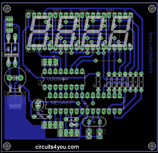
Flow meter PCB Layout
Flow meter Arduino Code
Coding is done using Arduino Software. we are displaying LPM on the display with two decimal point places. We are using “TimerOne” Library for display scan time generation.
/* Flow Meter using 4-Digit 7-segment Display Circuits4you.com Arduino UNO, ATMega328 */
#include <TimerOne.h>
const int SEG3=14;
const int SEG2=15;
const int SEG1=16;
const int SEG0=17;
const int dp=6;
const int a=7;
const int b=8;
const int c=9;
const int d=10;
const int e=11;
const int f=12;
const int g=13;
const int Relay=18;
const int Buzzer=19;
const int Sensor=2;
int cc=0;
char Value[4];
const char SegData[]={0x3F,0x06,0x5B,0x4F,0x66,0x6D,0x7D,0x07,0x7F,0x6F};
int Count=0;
volatile int FlowPulse; //measuring the rising edges of the signal
int Calc;
//=============================================================
// Setup
//=============================================================
void setup() { // initialize the digital pin as an output. Serial.begin(9600); pinMode(SEG0, OUTPUT); pinMode(SEG1, OUTPUT); pinMode(SEG2, OUTPUT); pinMode(SEG3, OUTPUT); pinMode(dp, OUTPUT); pinMode(a, OUTPUT); pinMode(b, OUTPUT); pinMode(c, OUTPUT); pinMode(d, OUTPUT); pinMode(e, OUTPUT); pinMode(f, OUTPUT); pinMode(g, OUTPUT); pinMode(Relay, OUTPUT); pinMode(Buzzer, OUTPUT); pinMode(Sensor,INPUT); digitalWrite(Buzzer,HIGH); delay(1000); digitalWrite(Buzzer,LOW); digitalWrite(Relay,LOW); //Initialize Display Scanner cc=0; Timer1.initialize(5000); // set a timer of length 100000 microseconds (or 0.1 sec - or 10Hz => the led will blink 5 times, 5 cycles of on-and-off, per second) Timer1.attachInterrupt( timerIsr ); // attach the service routine here attachInterrupt(0, rpm, RISING); //and the interrupt is attached on Pin 2 (INT 0)
}
//=============================================================
// Loop
//=============================================================
void loop() { char cnt[4]; //Display Count on Segments sprintf(cnt,"%04d",Calc); //We get ASCII array in Volt Serial.println(Calc); //Print Count on Serial for debug Value[0]=cnt[0] & 0x0F; //Anding with 0x0F to remove upper nibble Value[1]=cnt[1] & 0x0F; //Ex. number 2 in ASCII is 0x32 we want only 2 Value[2]=cnt[2] & 0x0F; Value[3]=cnt[3] & 0x0F; FlowPulse = 0; //Set NbTops to 0 ready for calculations sei(); //Enables interrupts delay (1000); //Wait 1 second cli(); //Disable interrupts Calc = FlowPulse * 100.0; //(Pulse frequency x 60) / 7.5Q, = flow rate in L/hour Calc = Calc / 7.5; if(Calc < 700) { Count++; if(Count>10) { digitalWrite(Buzzer,HIGH); digitalWrite(Relay,HIGH); Count=0; } } else { digitalWrite(Buzzer,LOW); digitalWrite(Relay,LOW); Count=0; }
}
void rpm () //This is the function that the interupt calls
{ FlowPulse++; //This function measures the rising and falling edge of the hall effect sensors signal
}
//=============================================================
// Generates Digit
//=============================================================
void DisplayDigit(char dt)
{ if((dt & 0x80) == 0x00) {digitalWrite(dp,LOW);} else {digitalWrite(dp,HIGH);} if((dt & 0x40) == 0x00) {digitalWrite(g,LOW);} else {digitalWrite(g,HIGH);} if((dt & 0x20) == 0x00) {digitalWrite(f,LOW);} else {digitalWrite(f,HIGH);} if((dt & 0x10) == 0x00) {digitalWrite(e,LOW);} else {digitalWrite(e,HIGH);} if((dt & 0x08) == 0x00) {digitalWrite(d,LOW);} else {digitalWrite(d,HIGH);} if((dt & 0x04) == 0x00) {digitalWrite(c,LOW);} else {digitalWrite(c,HIGH);} if((dt & 0x02) == 0x00) {digitalWrite(b,LOW);} else {digitalWrite(b,HIGH);} if((dt & 0x01) == 0x00) {digitalWrite(a,LOW);} else {digitalWrite(a,HIGH);}
}
//===================================================================
//	TIMER 1 OVERFLOW INTTERRUPT FOR DISPALY
//===================================================================
void timerIsr()
{	cc++;	if(cc==5) //We have only 4 digits	{cc=1;}	Scanner();	TCNT0=0xCC;
}
//===================================================================
//	SCAN DISPLAY FUNCTION
//===================================================================
void Scanner()
{ switch (cc) //Depending on which digit is selcted give output { case 1: digitalWrite(SEG3,LOW); DisplayDigit(SegData[Value[0]]); digitalWrite(SEG0,HIGH); break; case 2: digitalWrite(SEG0,LOW); DisplayDigit(SegData[Value[1]] | 0x80); //Decimal Point digitalWrite(SEG1,HIGH); break; case 3: digitalWrite(SEG1,LOW); DisplayDigit(SegData[Value[2]]); digitalWrite(SEG2,HIGH); break; case 4: digitalWrite(SEG2,LOW); DisplayDigit(SegData[Value[3]]); digitalWrite(SEG3,HIGH); break; }
}
//===================================================================
A magnetic flow meter, or mag meter, is a volumetric flow meter with no moving parts and is ideal for wastewater applications or any other dirty liquid that is conductive.
Magnetic flow meters will generally not work with hydrocarbons, distilled water, or many non-aqueous solutions. Magnetic flow meters are often selected and specified for applications because they are obstruction-less, cost-effective for aggressive chemicals and slurries, and provide highly accurate volumetric flow measurement. A range of liner materials, electrode options, and line sizes accommodate a wide variety of process applications.
Operation Theory
Magnetic flow meters utilize Faraday’s Law of Electromagnetic Induction to determine the velocity of a liquid flowing through a pipe. Faraday’s Law forms the basis for electrical generation systems where wires travel through a magnetic field and produce a voltage. In magnetic flow meters, a magnetic field is generated and channeled into the liquid flowing through the pipe.
To accomplish this, the electromagnetic coils can be located outside of the pipe (flow tube), however, the flow tube must be non-magnetic to allow penetration of the magnetic field into the liquid.
Locating the coils internal to the flow meter (closer to the liquid) can reduce the electrical power necessary to deliver the magnetic field, as well as reduce the size of the flow meter and fabrication costs.
Following Faraday’s Law, the flow of a conductive liquid through the magnetic field will cause a voltage signal to be generated. This signal is sensed with electrodes located on the flow tube walls. When the coils are located externally, a non-conductive liner is installed inside the flow tube to electrically isolate the electrodes and prevent the signal from being shorted. For similar reasons, non-conductive materials are used to isolate the electrodes for internal coil designs. The fluid itself is the conductor that will flow through the magnetic field and generate a voltage signal at the electrodes. When the fluid moves faster, more voltage is generated. Faraday’s Law states the voltage generated is proportional to the movement of the flowing liquid. The transmitter processes the voltage signal to determine liquid flow.
How to Use Magnetic Flow Meters
Magnetic flow meters measure the velocity of conductive liquids in pipes, such as water, acids, caustic, and slurries. Magnetic flow meters can measure properly when the electrical conductivity of the liquid is greater than approximately 5μS/cm. Using magnetic flow meters on fluids with low conductivity, such as deionized water, boiler feed water, or hydrocarbons, can cause the flow meter to turn off and measure zero flow.
These flow meters do not obstruct flow, so they can be used for clean, sanitary, dirty, corrosive and abrasive liquids. Magnetic flow meters can be applied to the flow of liquids that are conductive, so hydrocarbons and gases cannot be measured with this technology due to their non-conductive nature and gaseous state, respectively.
Magnetic flow meters do not require much upstream and downstream straight runs so they can be installed in relatively short meter runs. Magnetic flow meters typically require 5-10 diameters of upstream straight run and 5-2 diameters of downstream straight run measured from the plane of the magnetic flow meter electrodes.
Industries that Use Magnetic Flow Meters
Magnetic Flow Meters represent about 24% of all flow meters sold today. Applications for dirty liquids are found in the water, wastewater, mining, mineral processing, power, pulp and paper, and chemical industries. Water and wastewater applications include custody transfer of liquids in force mains between water/wastewater districts. Magnetic flow meters are used in water treatment plants to measure treated and untreated sewage, process water, water, and chemicals. Mining and mineral process industry applications include process water and process slurry flows and heavy media flows.
With proper attention to materials of construction, the flow of highly corrosive liquids (such as acid and caustic) and abrasive slurries can be measured. Corrosive liquid applications are commonly found in chemical industry processes and in chemical feed systems used in most industries. Slurry applications are commonly found in the mining, mineral processing, pulp and paper, and wastewater industries.
Magnetic flow meters are often used where the liquid is fed using gravity. Be sure that the orientation of the flow meter is such that the flow meter is completely filled with liquid. Failure to ensure that the flow meter is completely filled with liquid can significantly affect the flow measurement.
Use caution when operating magnetic flow meters in vacuum service because some magnetic flow meter liners can collapse and be sucked into the pipeline in vacuum service, catastrophically damaging the flow meter. Note that vacuum conditions can occur in pipes that seemingly are not exposed to vacuum service such as pipes in which a gas can condense (often under abnormal conditions). Similarly, an excessive temperature in magnetic flow meters (even briefly under abnormal conditions) can result in permanent flow meter damage.
Typical Applications
For slurry service, be sure to size magnetic flow meters to operate above the velocity at which solids settle (typically 1.5 – 2 ft/sec), in order to avoid filling the pipe with solids that can affect the measurement and potentially stop the flow. Magnetic flow meters for abrasive service are usually sized to operate at low velocity (typically below 5 – 6 ft/sec) to reduce wear. In abrasive slurry service, the flow meter should be operated above the velocity at which solids will settle, despite increased wear. These issues may change the range of the flow meter, so its size may be different than the size for an equivalent flow of clean water.
Application Considerations for Magnetic Flow Meters
Do not operate a magnetic flow meter near its electrical conductivity limit because the flow meter can turn off. Provide an allowance for the changing composition and operating conditions that can change the electrical conductivity of the liquid.
In typical applications, magnetic flow meters are sized so that the velocity at maximum flow is approximately 75% of the max flow of the meter. Differential pressure constraints and/or process conditions may preclude application of this general guideline. For example, gravity fed pipes may require a larger magnetic flow meter to reduce the pressure drop to allow the required amount of liquid to pass through the magnetic flow meter without backing up the piping system. In this application, operating at the same flow rate in the larger flow meter will result in a lower liquid velocity as compared to the smaller flow meter.
Advantages and Disadvantages
There are numerous benefits to using electromagnetic flow meters to perform fluid flow measurements. They are generally non-invasive and have no moving parts, reducing the risk of breakdowns and the frequency of repairs. A decrease in flow meter pressure is also usually no greater than that of an equivalent pipe length, reducing the piping costs. Some of the other major advantages provided by magnetic flow meters include:
- Power usage is relatively low, with electrical power requirements as low as 15 watts for some models.
- They are mechanically obstruction-less and can be equipped with abrasion-resistant liners, making them effective for measuring slurries and other erosive fluids.
- They are capable of dealing with most kinds of acids and bases, as well as water and water-based solutions, due to lining materials that are both insulators and corrosion resistant.
- Relatively small amounts of electrode metals are needed for magnetic flow meters.
- They can measure both very low flows and very high volume flow rates, with a minimum diameter of roughly 0.125 inches and a maximum volume of up to 10 cubic feet.
- They can usually measure multi-directional flow, either upstream or downstream.
Despite these advantages, magnetic flow meters also present certain difficulties for flow rate measurement. These flow meters are only effective on conductive fluids, and materials such as unmixed hydrocarbons and gases cannot be measured. However, magnetic materials themselves may also present problems, as hydrodynamic effects can alter the normal flow pattern and disturb the velocity rate enough to interfere with operations. Depending on their size and capacity, magnetic flow meters can be relatively heavy, and those with higher corrosion and abrasion resistance can be expensive.
If you want to know if magnetic flow meters might be right for your application contact us today. Our team of flow experts can help you to find the right product for your application.
See how our process solutions team can help improve quality, increase efficiency, and reduce risk
Please enable cookies.
We are checking your browser… www.electrical4u.com
Why do I have to complete a CAPTCHA?
Completing the CAPTCHA proves you are a human and gives you temporary access to the web property.
What can I do to prevent this in the future?
If you are on a personal connection, like at home, you can run an anti-virus scan on your device to make sure it is not infected with malware.
Cloudflare Ray ID: 6e8a87968bbd9781
•
Your IP: 45.91.203.94
•
Performance & security by Cloudflare


